|
|
#46
 05-26-2014, 06:05 PM
|
|||
|
|||
|
Quote:
PS...I was so lucky to have that extra granite top to borrow from my Dad, but he's mentioned that he wants it back when I'm done building. I guess this just means that I need to order the stewmac dread guitar kit so I'm not ever "done building". 

|
|
#47
05-26-2014, 06:08 PM
|
|||
|
|||
|
Quote:
|
|
#48
05-26-2014, 06:22 PM
|
|||
|
|||
|
I've made some great progress with the holiday weekend. Hope you all enjoy this update of photos as much as I do!
I started with bracing the top, but the braces did come very well prepared for gluing so I sanded them down with 120-grit to get a better surface for the joint. You can see the difference in this photo, the top half is sanded, the bottom half not yet. 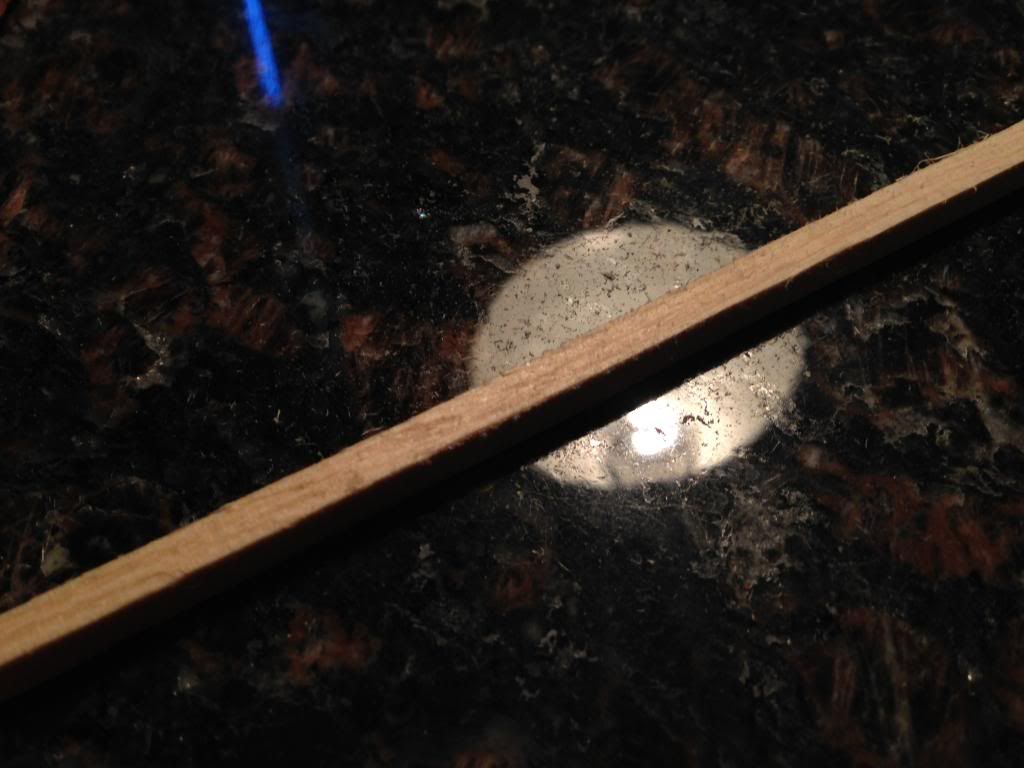 Always have to do the dry fitting without glue first: 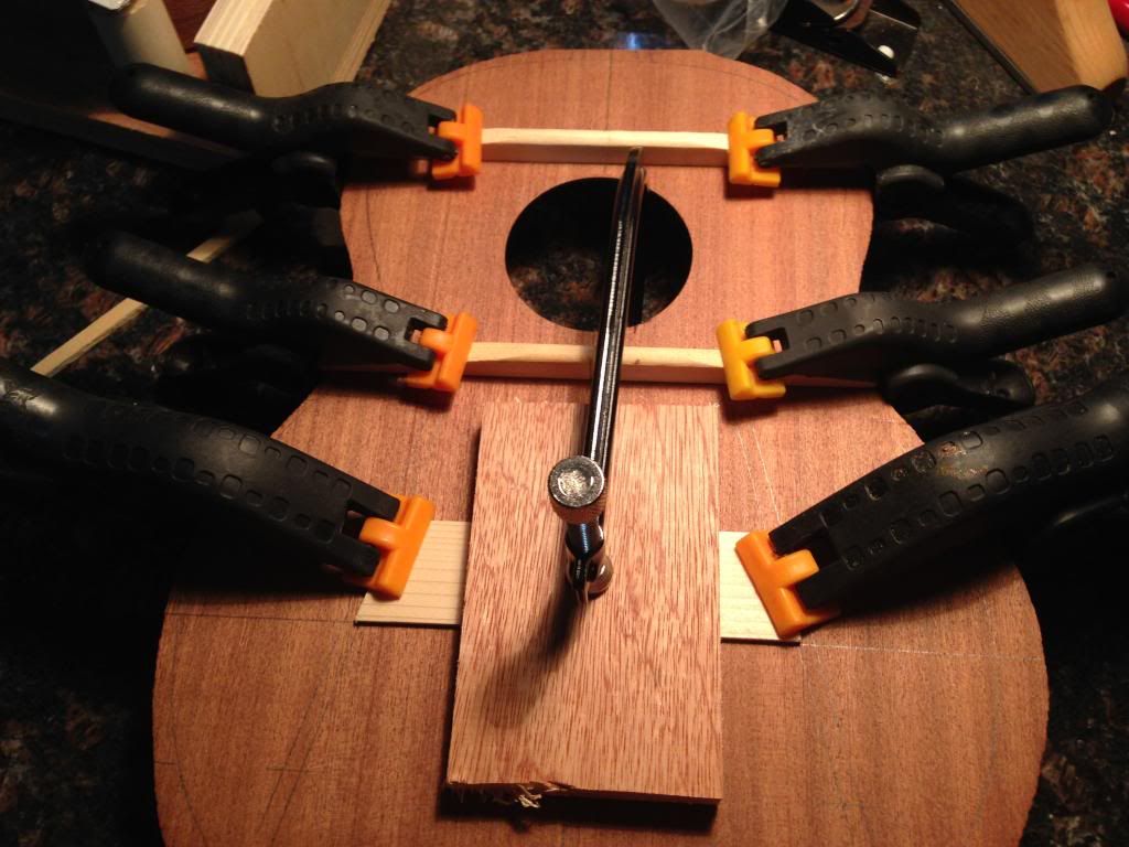 Each clamping spot gets the light test and this passed: 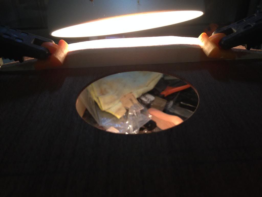 I wasn't comfortable with this squeeze out so...  I changed the clamp and this looks much better:  Final glue-up, let it sit overnight.  You can see in the last picture that I didn't glue in the fan braces yet, this is the disadvantage of not having a go-bar deck. 
|
|
#49
05-26-2014, 06:40 PM
|
|||
|
|||
|
While dry fitting the fan braces, I noticed the angle of the bridgeplate wasn't cut correctly:
 So I decided to trim it so it lined up with the template better: 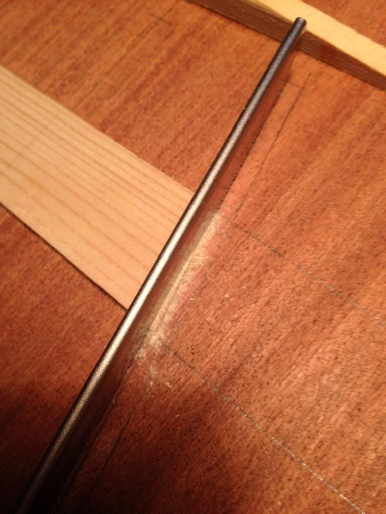 It lines up much better: 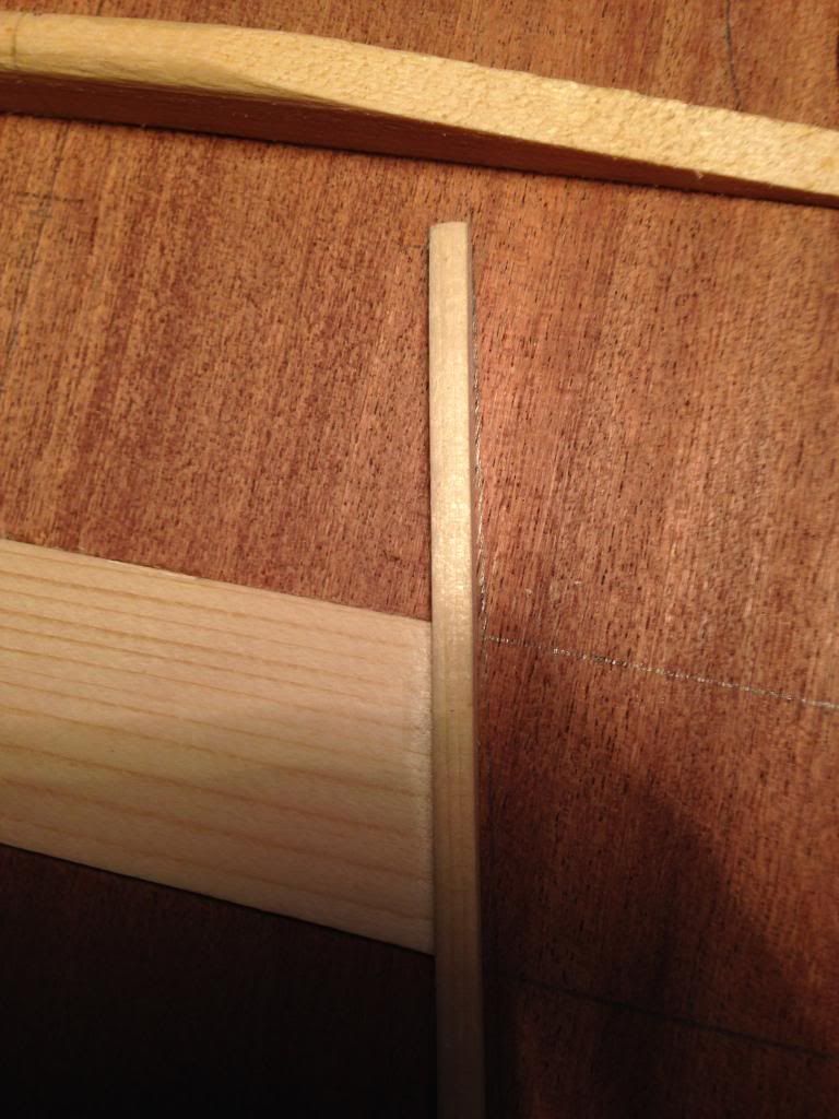 I forgot to take a picture, but I made sure to do a dry fit before I added glue. Here's the final glue-up of the fan braces: 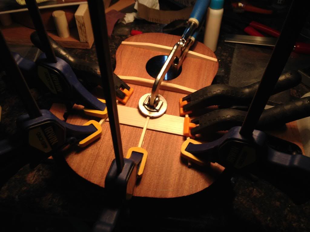
|
|
#50
05-26-2014, 06:50 PM
|
|||
|
|||
|
While the top was drying, I started to carve the back braces. I have to give a huge thanks to the MyaMoe team for their "Birth of a MyaMoe" YouTube series as I've learned a lot, the carving is just one of the many concepts!
Quote:
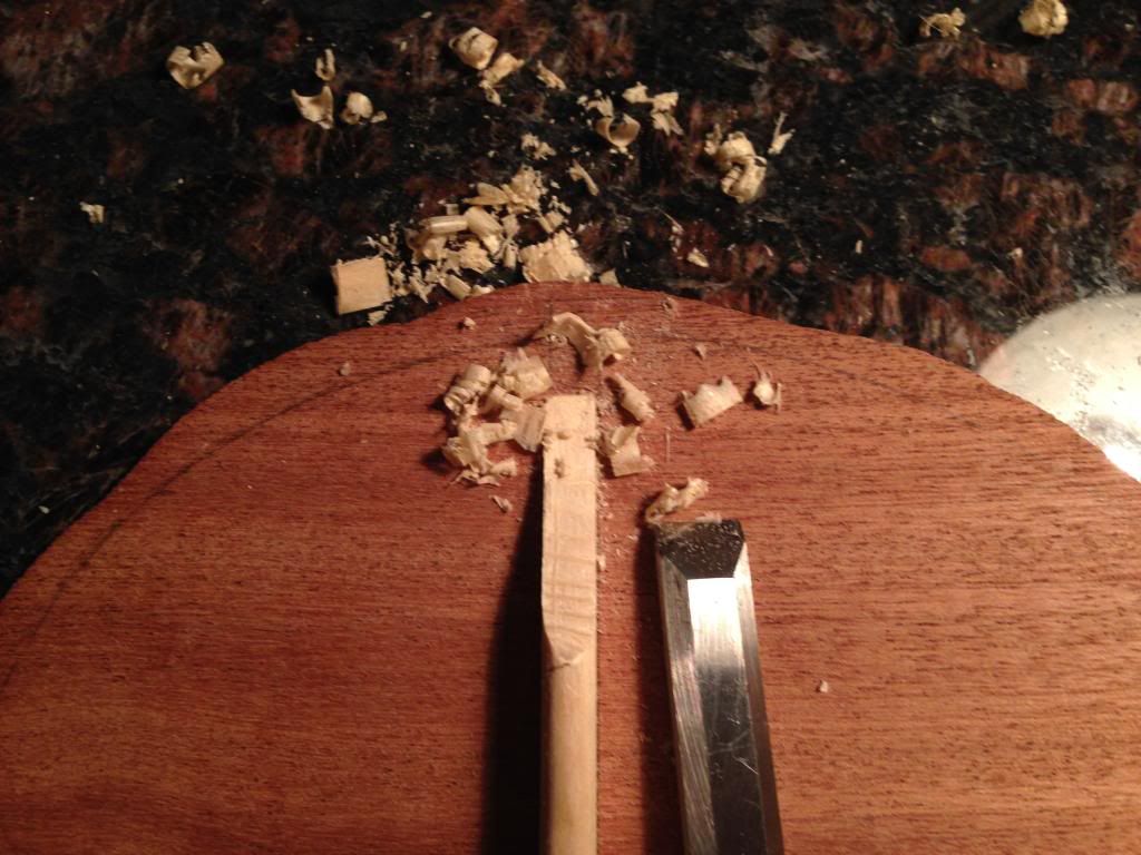 Shaping the braces to have more of a peak: 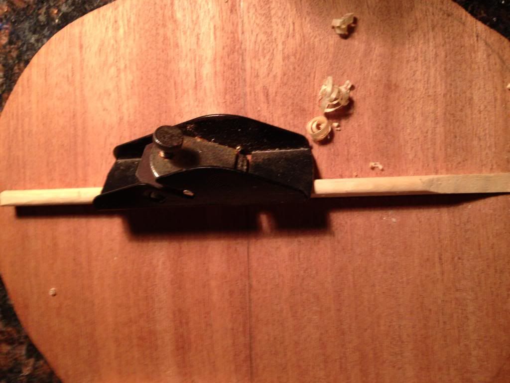 Sanded the edges smooth with 100-grit to make it look nicer: 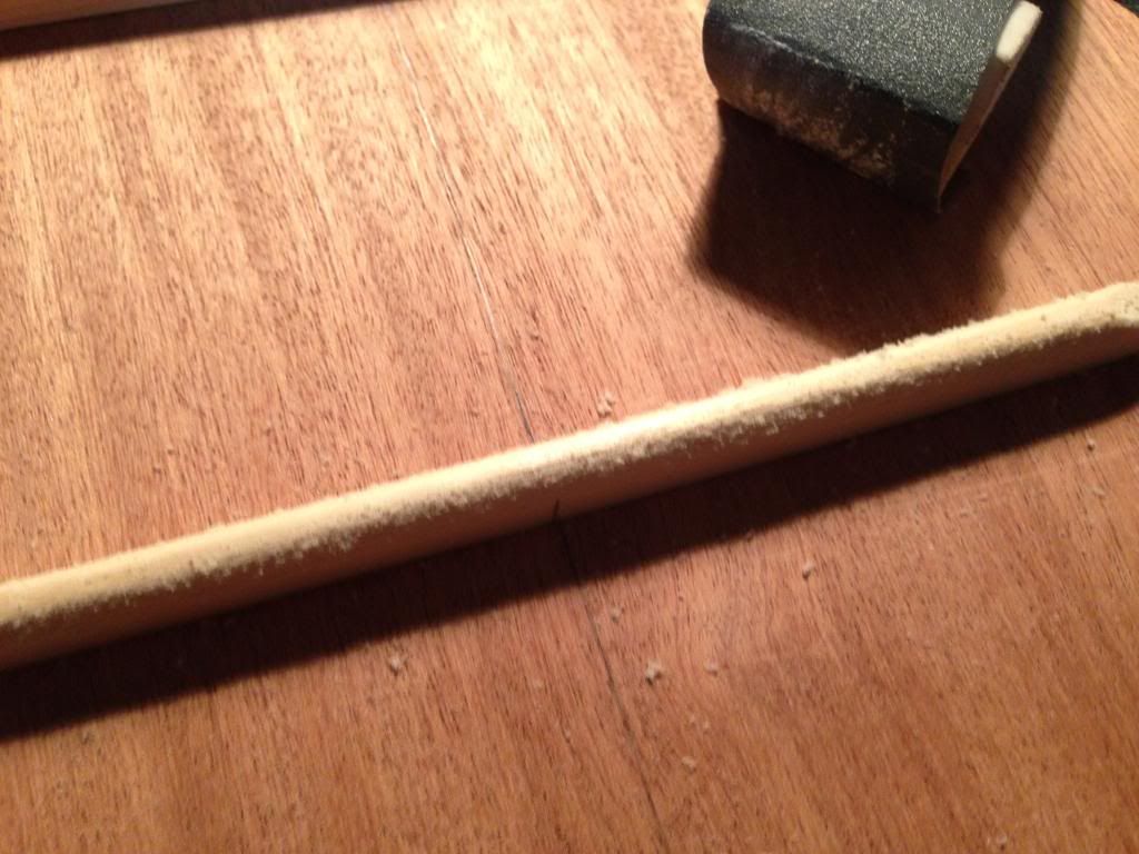 Here's the lower back brace all done, not bad for my very first brace carving ever: 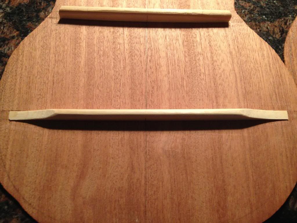 Working on the top bracing 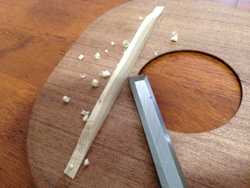 All the carving done: 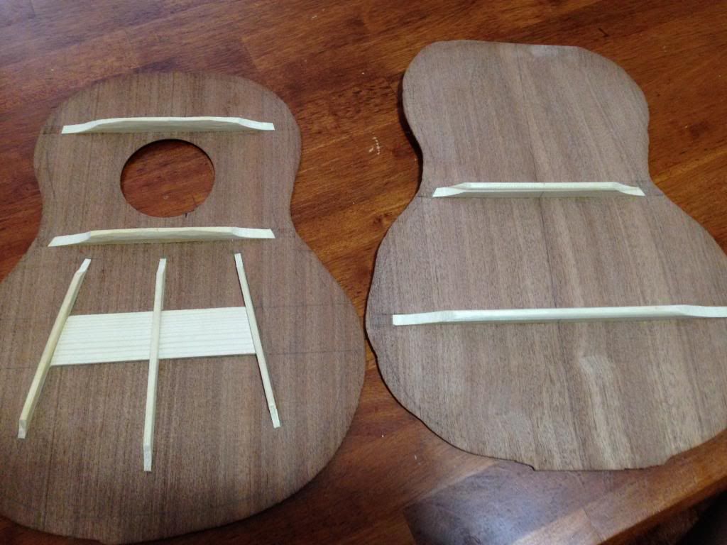 Jackie and I added our little "Made in Guam" stamp: 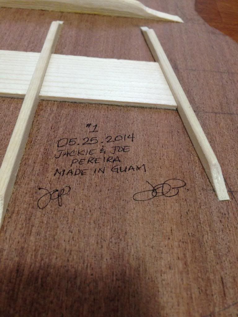 This is also the point at which I glued our soundhole label onto the back, sorry I forgot to take a picture. Last edited by joeguam; 05-26-2014 at 09:32 PM.
|
|
#51
05-26-2014, 06:58 PM
|
|||
|
|||
|
To glue the top, I needed to add the nails to the jig to fasten the rubber bands:
 Used the centerlines to line up the neck/heel block ends (made sure to add the wax paper!): 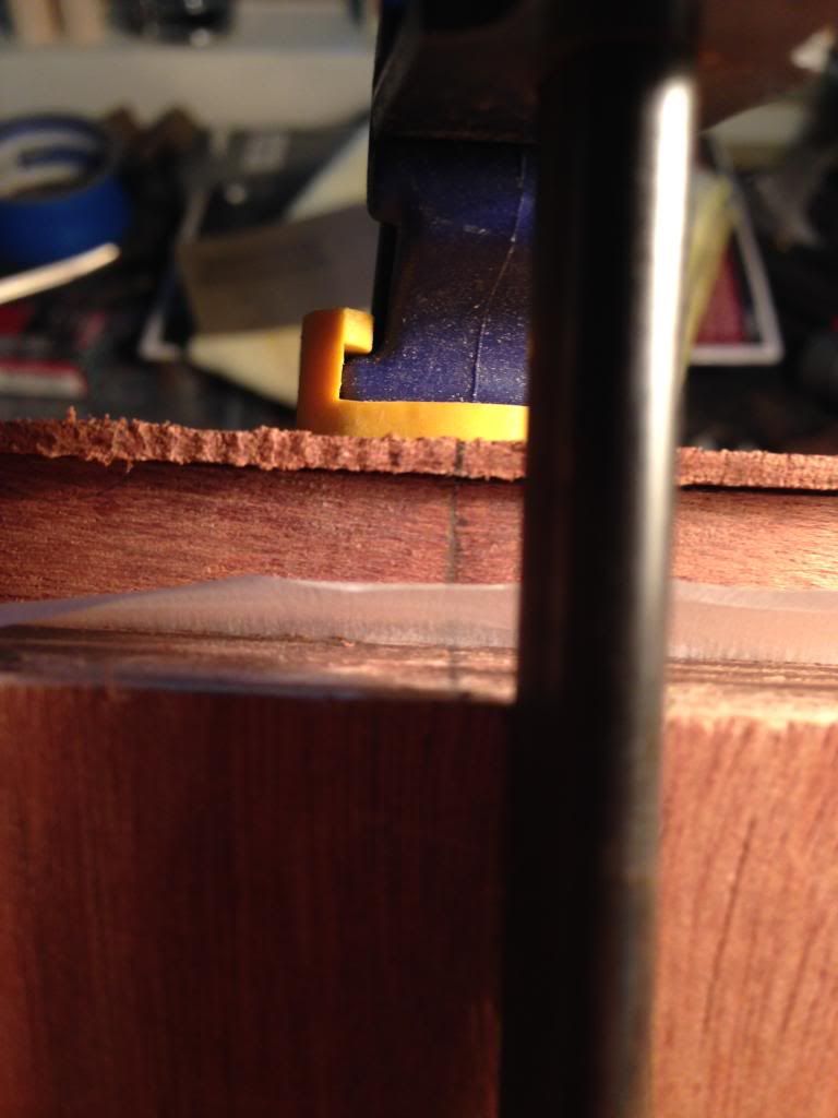 Finished the dry fit, but didn't do the rubber bands as they were more for reinforcement than anything: 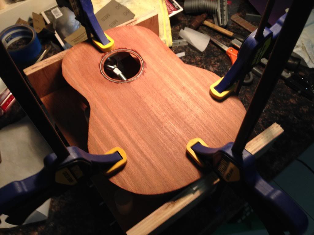 Here's the final glue-up, notice anything strange? 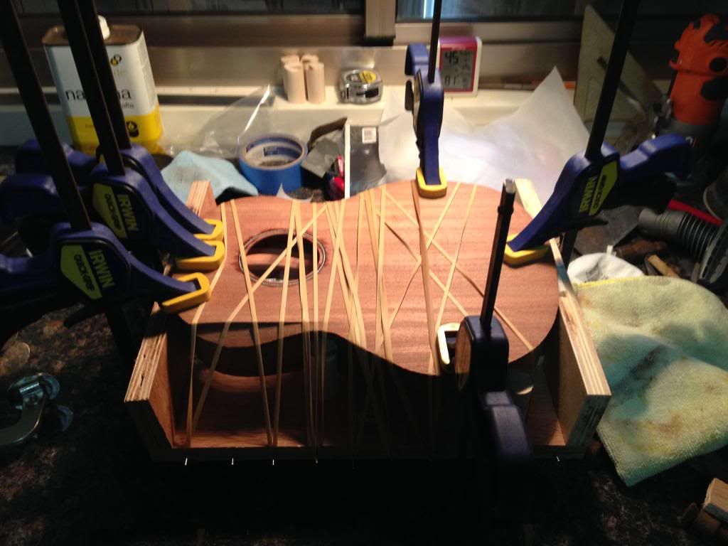
|
|
#52
05-26-2014, 07:13 PM
|
|||
|
|||
|
I was real bummed because while installing the rubber band, I noticed that it was deforming the top wood instead of applying proper clamping pressure and direction. I should've released the pressure of the rubber band right when I noticed it, but instead I had confidence in the kit instructions and figured this is how it was supposed to work...lesson learned.
Quote:
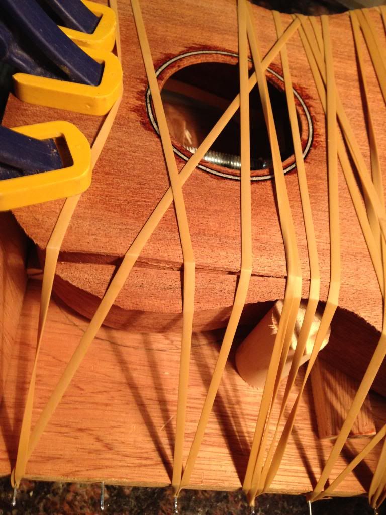 Regardless, I still wanted to repair it first before trimming the overhang. I used titebond and lightly clamped it: 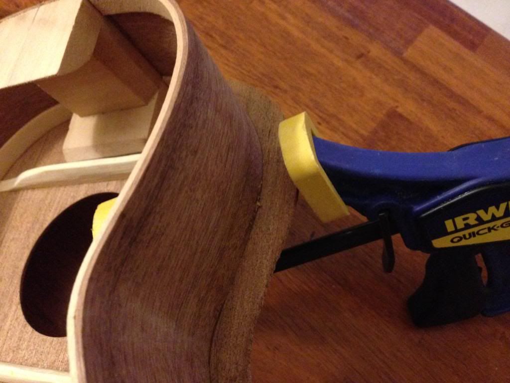 You can barely notice it was ever cracked: 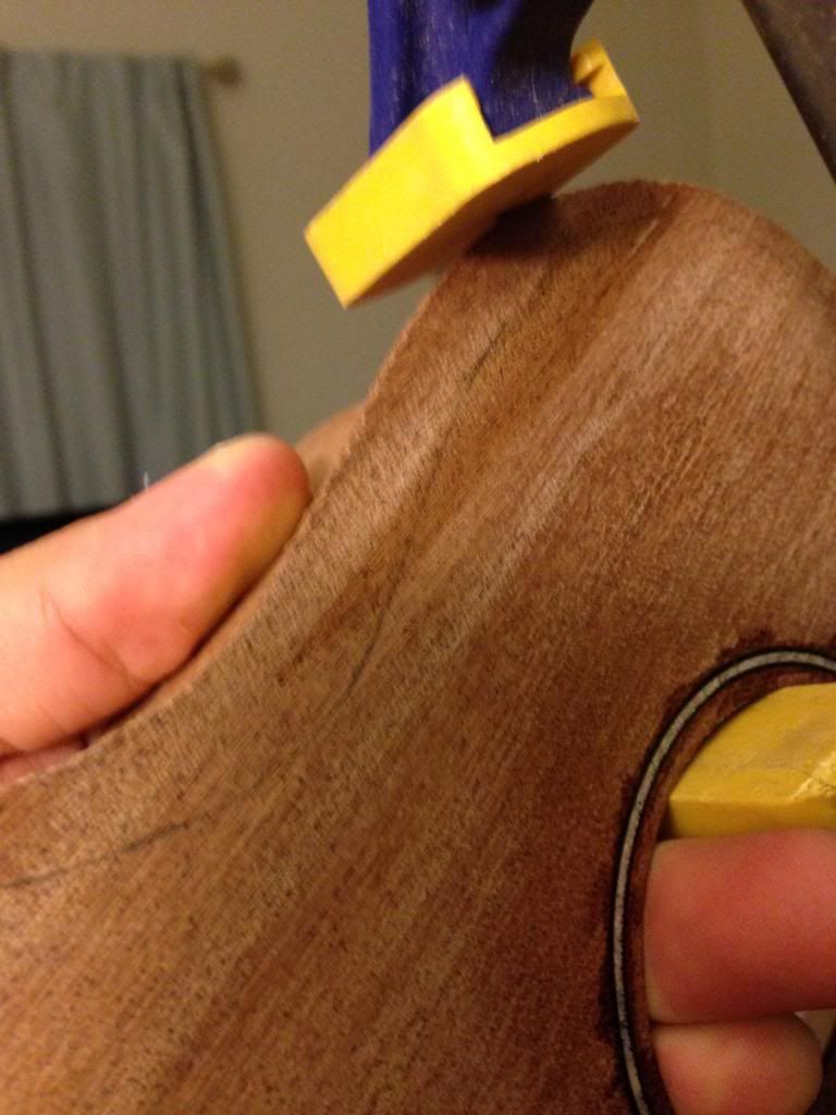 Whew, disaster averted!
|
|
#53
05-26-2014, 07:25 PM
|
|||
|
|||
|
Before I start this section, I have to once again say thank you to the MyaMoe team for their "Birth of a MyaMoe" YT series as Gordon's video and tips of how to trim-route the top was really helpful for me!
To trim the top to the sides, I used my Rigid mini router and a flush-cut router bit from Home Depot. This isn't the fancy stuff that stewmac sells, but it works just as perfectly. 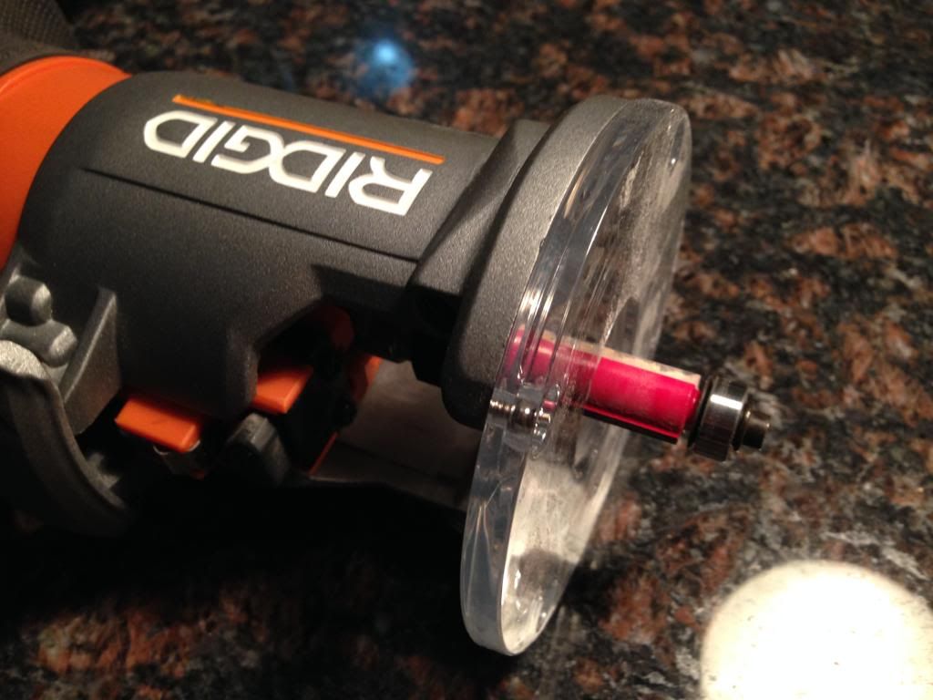 Since this is my first time flush cutting an instrument top, had to do a test cut to make sure I got a good feel for how the router bit will move. Quote:
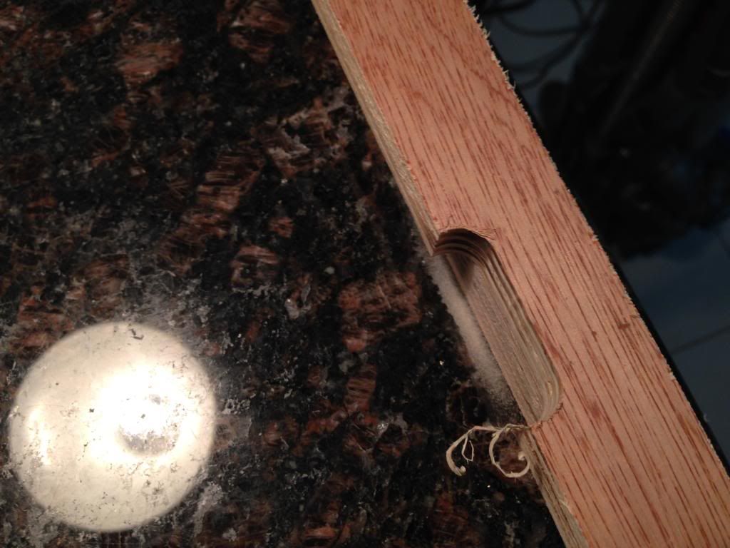 Set the depth of the bit appropriately, you never want to have any excess router bit blades exposed than necessary...it just asks for trouble. 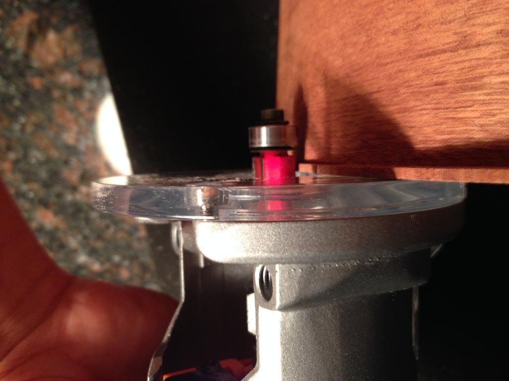 Here are the before pictures: 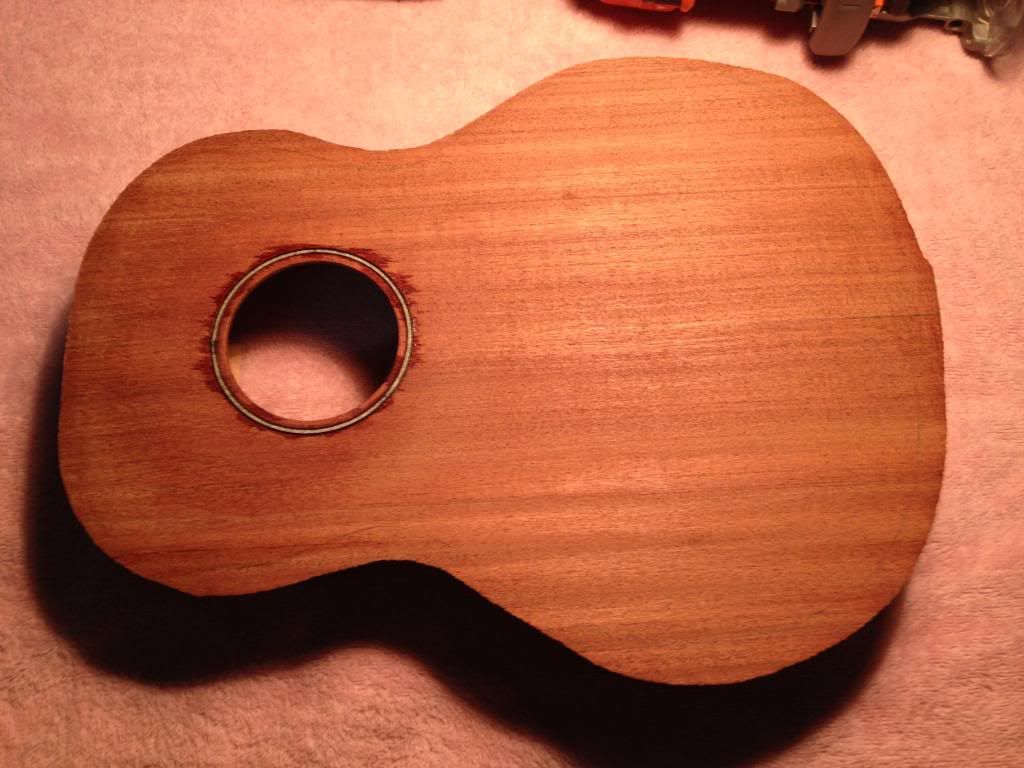 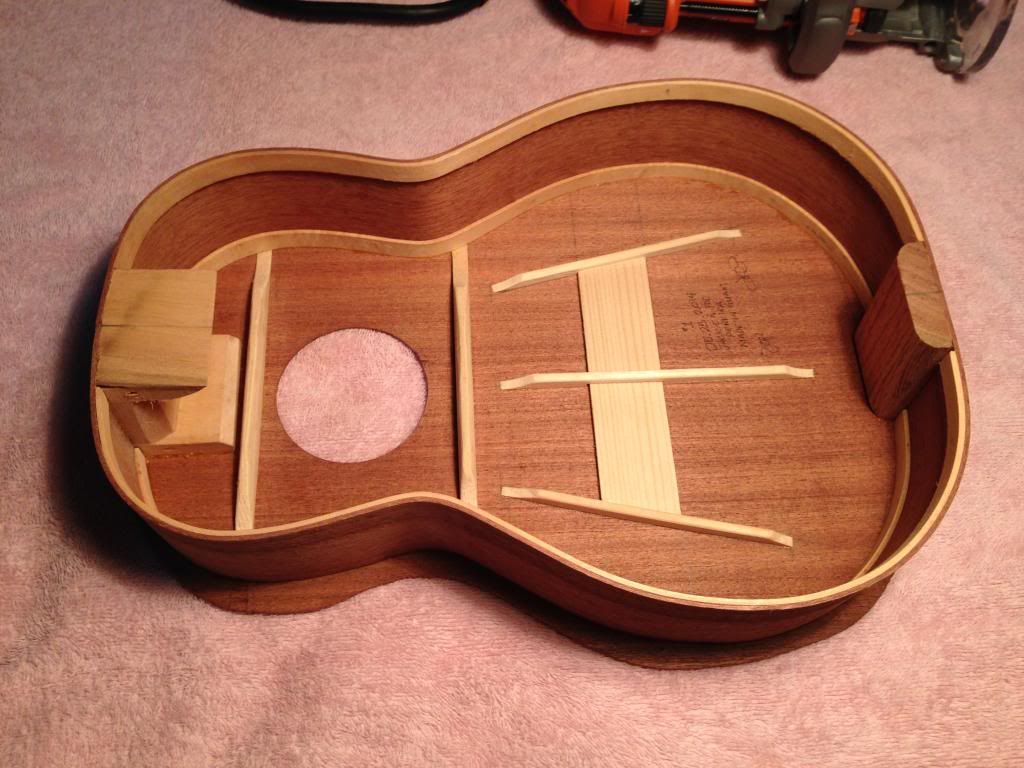 And here is the after photo. My apologies, however Jackie wasn't home and I had to keep both hands on the router so couldn't take pictures (stay tuned as Jackie took some great shots when I routed the back). 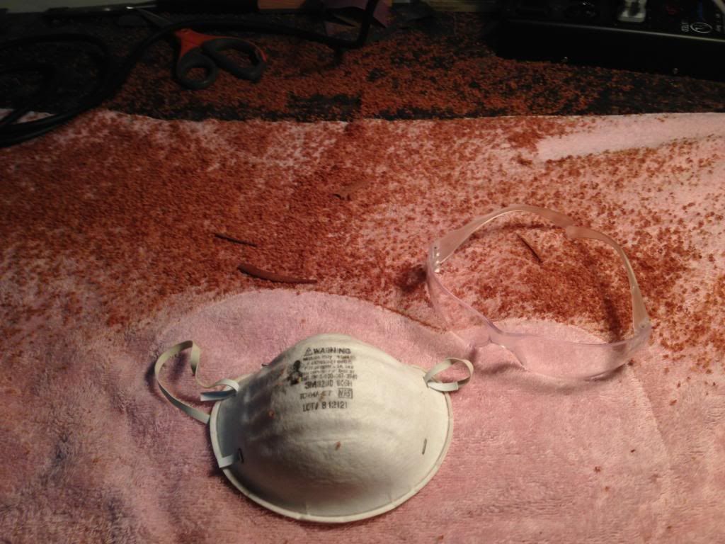 Always have to ensure your have your safety protective equipment!
|
|
#54
05-26-2014, 07:39 PM
|
|||
|
|||
|
The next step was to align and install the bolt to join the neck. First is to clamp the neck and body to an extremely flat surface, thankfully I have the granite top.
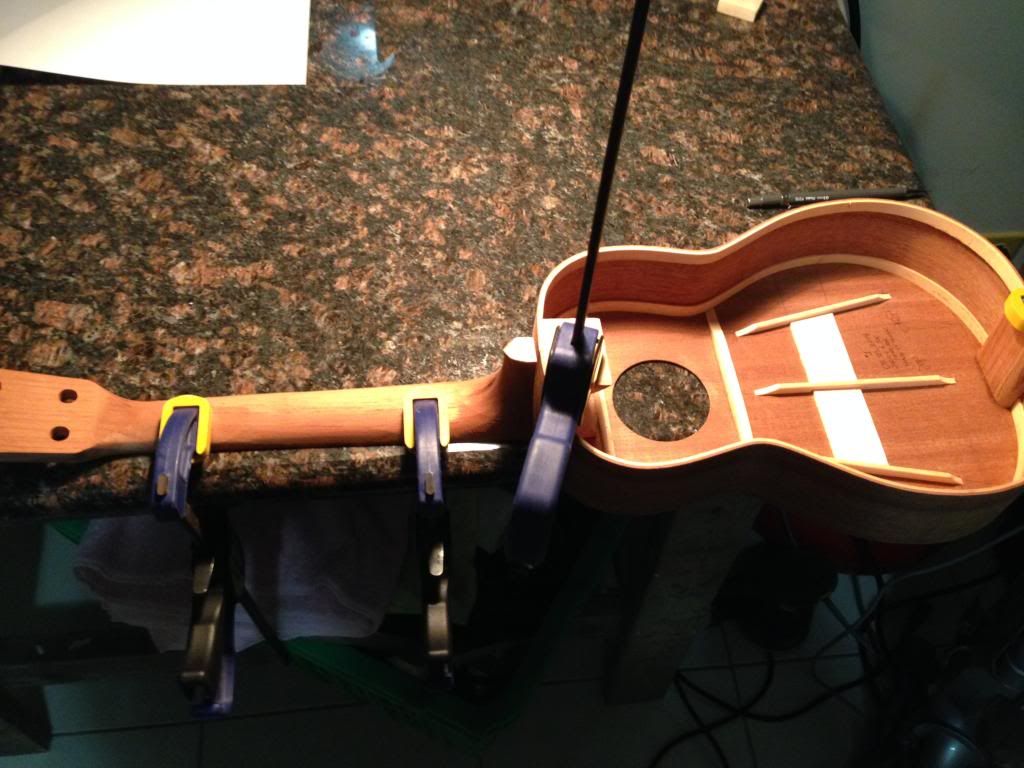 The truly flat surface of the granite revealed a major flaw - I didn't glue the top to the sides square! This is very disappointing because I disobeyed my very own LESSON LEARNED #3 to check for squareness. 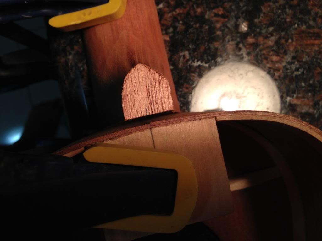 This picture shows how the sides are not square to the top. The square is sitting on the top right where the end of the fretboard will be glued and the ruler is dropping down where the neck heel will be glued. 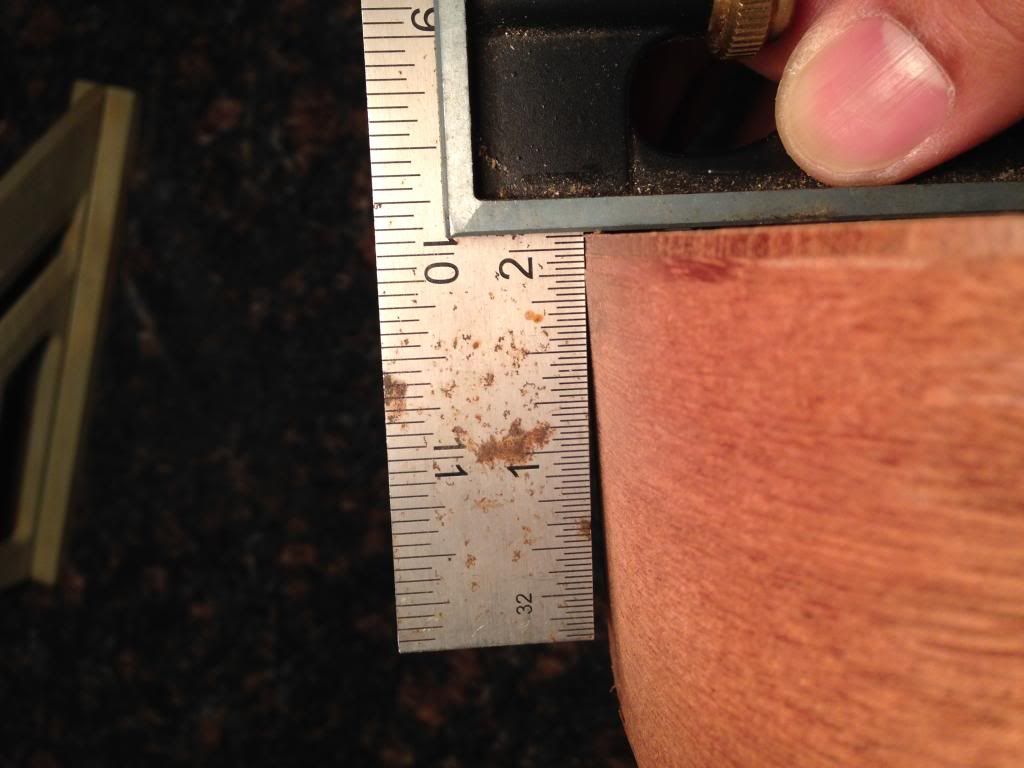 How did this happen you might ask? Apparently I extended the turnbuckle in the jig a bit too much. I took for granted that the ends of the jig would remain square so I tightened to a good fit...I guess it was too much. When I checked the jig after pulling the top out, it was not square and the turnbuckle had actually forced the sides a bit.
|
|
#55
05-26-2014, 07:57 PM
|
|||
|
|||
|
At this point I need to send a HUGE THANK YOU to Bruce Sexauer for his advice and help. The info he provided allowed me to decide how to proceed at this point. Thanks so much again Bruce!
Because the top was already trimmed and glued, I decided to reshape the neck heel to fit the body. Because the neck comes pre-shaped in the kit, this will cause the fretboard to be joined to the neck about 0.1" forward of the 14th fret. Bruce confirmed that this will work fine as long as the bridge is adjusted to accomodate the 0.1" shift. He also gave me confidence that 0.1" won't affect the bracing pattern at all. Here's the 0.1" gap that I have to account for: 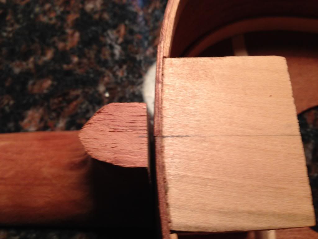 So I started by using 120-grit belt-sander belt taped to the body and started sanding by hand. 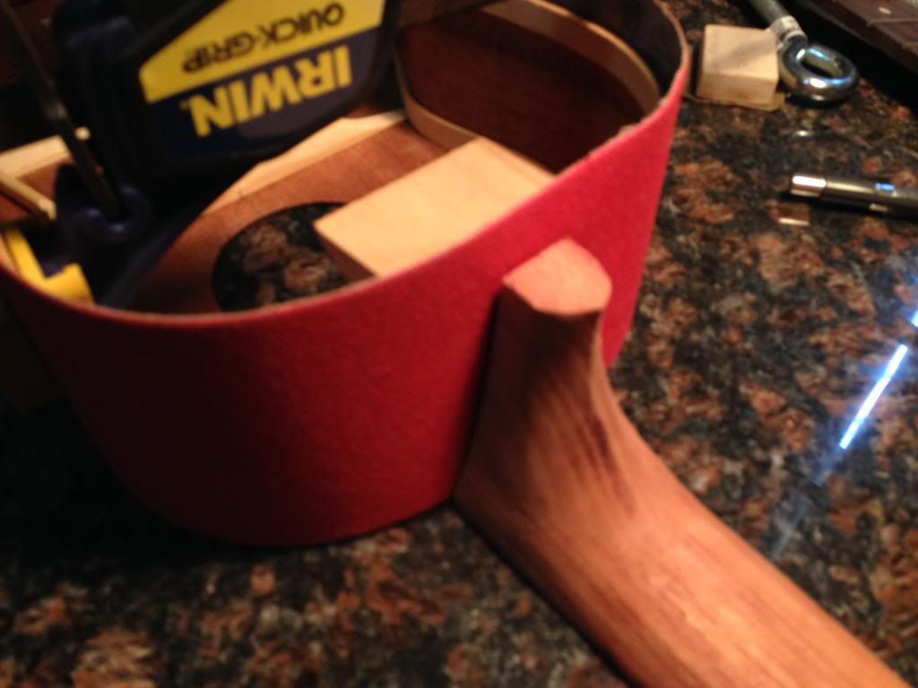 Marked off the heel to keep track of the material being sanded: 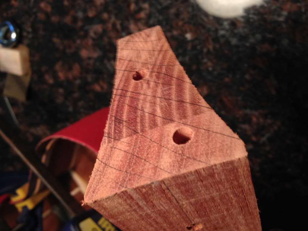 This quickly got very tedious and was just so ineffective because the very end of the heel closes to the granite was not sanding evenly. 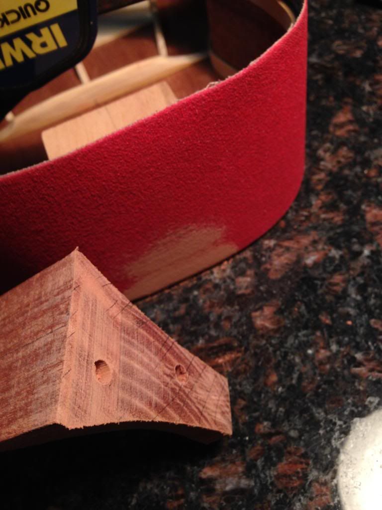 The only thing that worked very well was using 120-grit taped to my granite top, but this meant that I would have to sacrifice the radius. I was able to get it to seat pretty good. 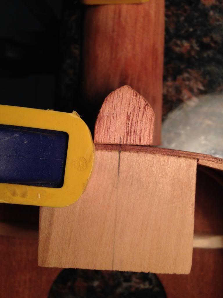 I made the determination that I didn't have the necessary tools to sand the radius into the neck heel. This is very unfortunate, however, the bolt + dowel + glue will give a more sufficient hold for the neck. It's not ideal but its definitely a lesson learned. For aesthetics, I will be filling in the gap with filler made from titebond and the saw dust.
|
|
#56
05-26-2014, 08:06 PM
|
|||
|
|||
|
The next step was to drill and install the threaded insert and bolt.
I forgot to take a picture, but I had to measure a good location for the threaded insert. For some reason, the neck came with pre-drilled holes. Not sure what these were for but they were annoying. Haha! I used a digital caliper to measure the distance from the top where I could drill to fit the insert. Then, I locked the digital caliper and used this same measurement to transfer the point to the body. I then used a 3/32 bit to drill a pilot hole. 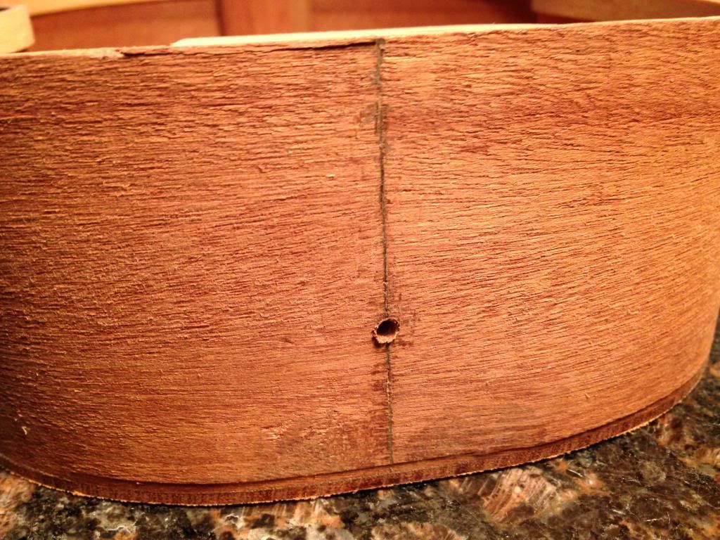 I then lined up and clamped the neck/body to the granite top and reversed the drill bit in the pilot hole. 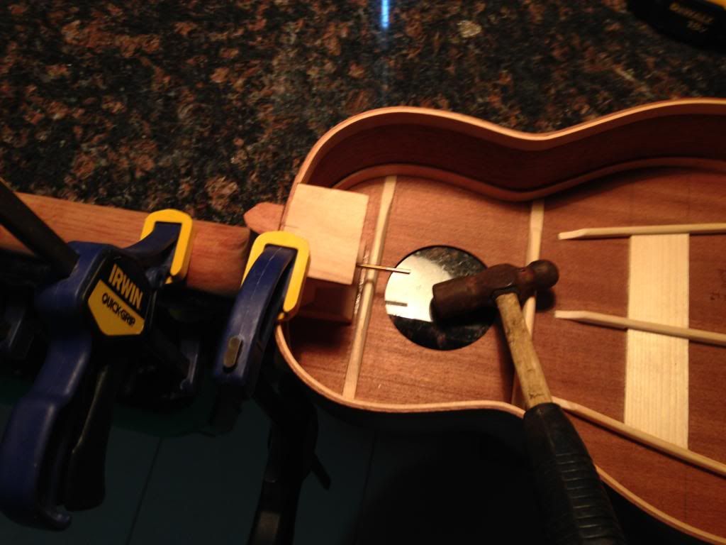 Using a small hammer, I gently tapped a mark in the neck heel to drill for the insert. It made a perfect starting pilot hole for the drill bit: 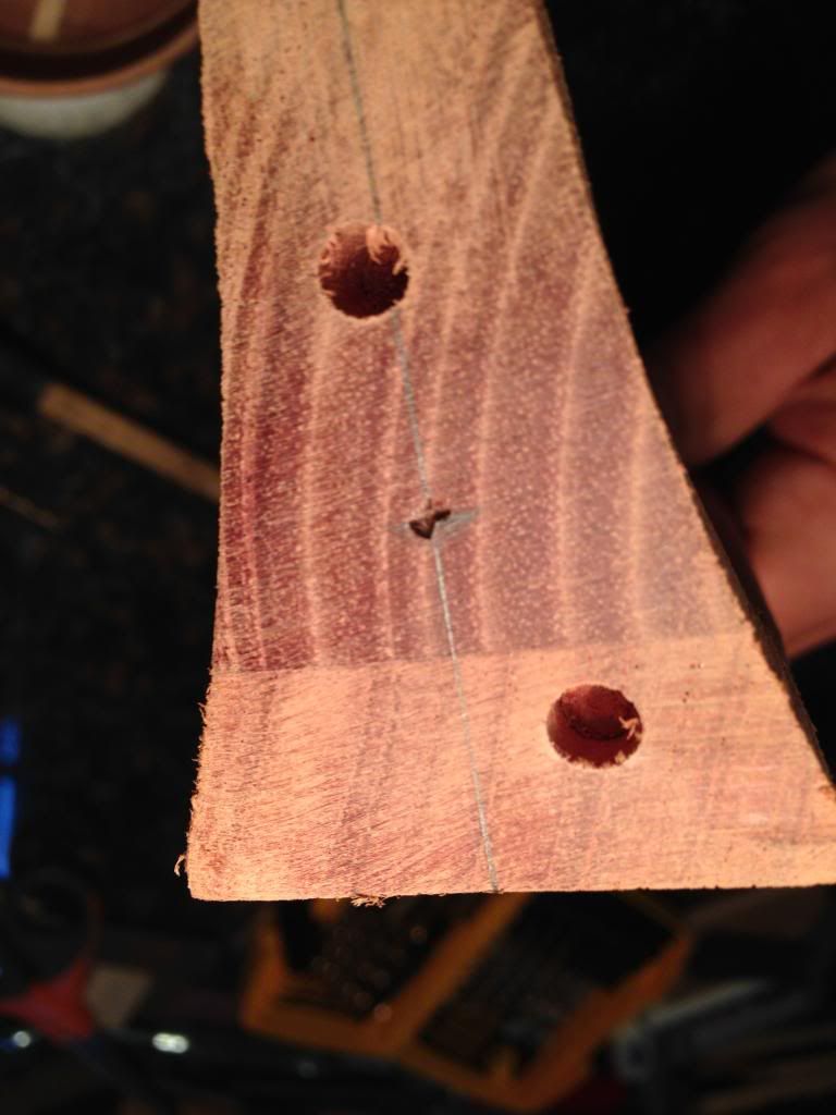 Here's the pilot hole for the threaded insert, this will be enlarged to 3/8" per the specifications of the threaded insert install instructions for hardwood. 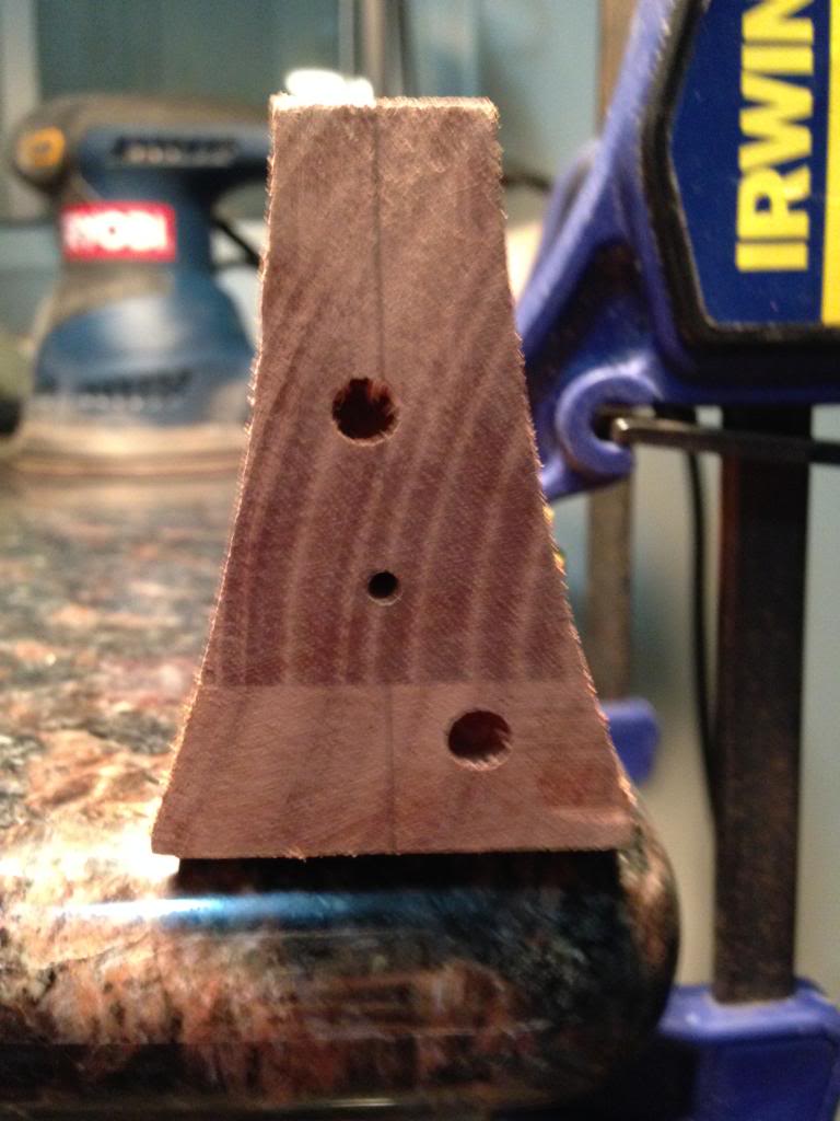
|
|
#57
05-26-2014, 08:11 PM
|
|||
|
|||
|
I wanted to thread the insert in slowly by hand so I used a long bolt with some wing nuts which served as levers. The single wing nut by the threaded insert is the "lock" to keep it in tension.
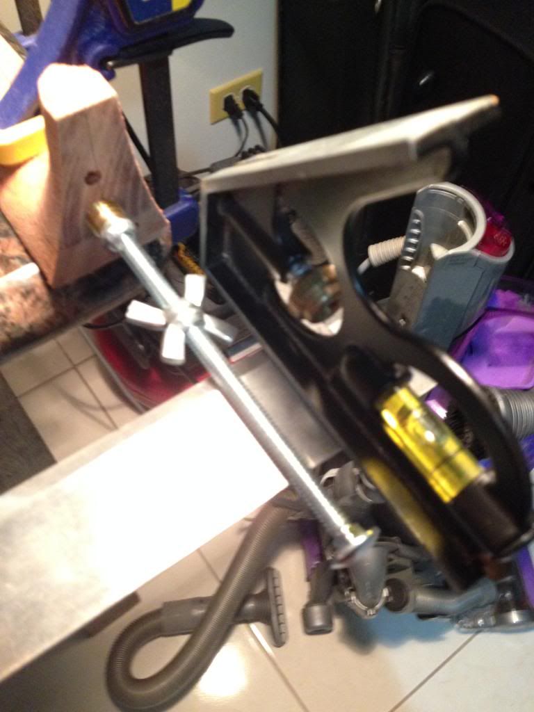 I went real slow and it came out really good! I was worried that it would crack the neck heel, but I followed the proper pilot hole instructions and used caution. 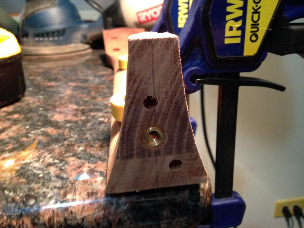 Even without the dowel, the neck and top line up perfectly flat! I was so amazed at how well this method worked. 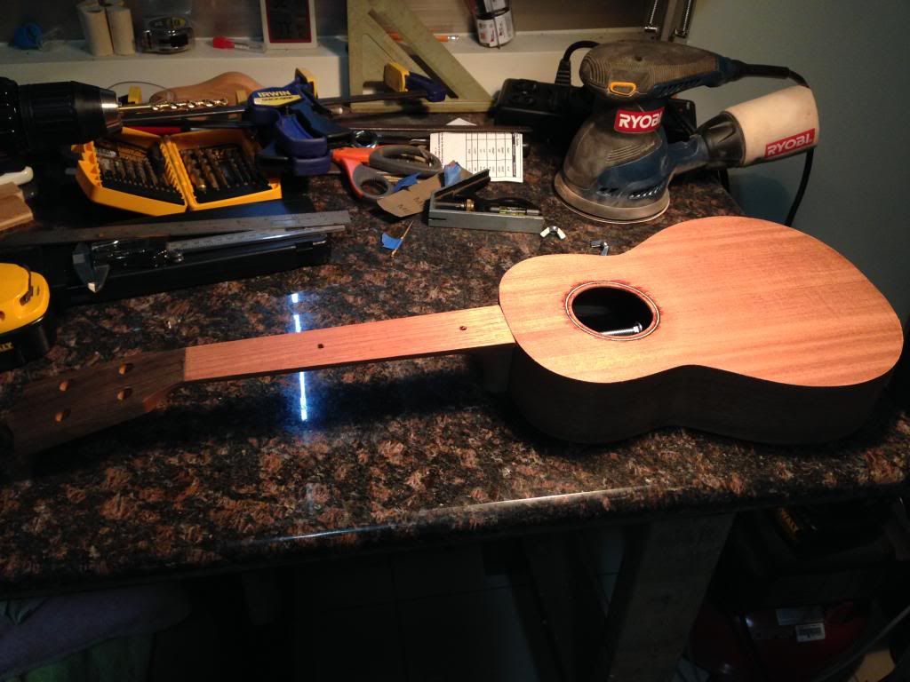 Here you can see how the heel is not radiused. I just have no feasible way of sanding a perfect radius to match with my limited tooling. 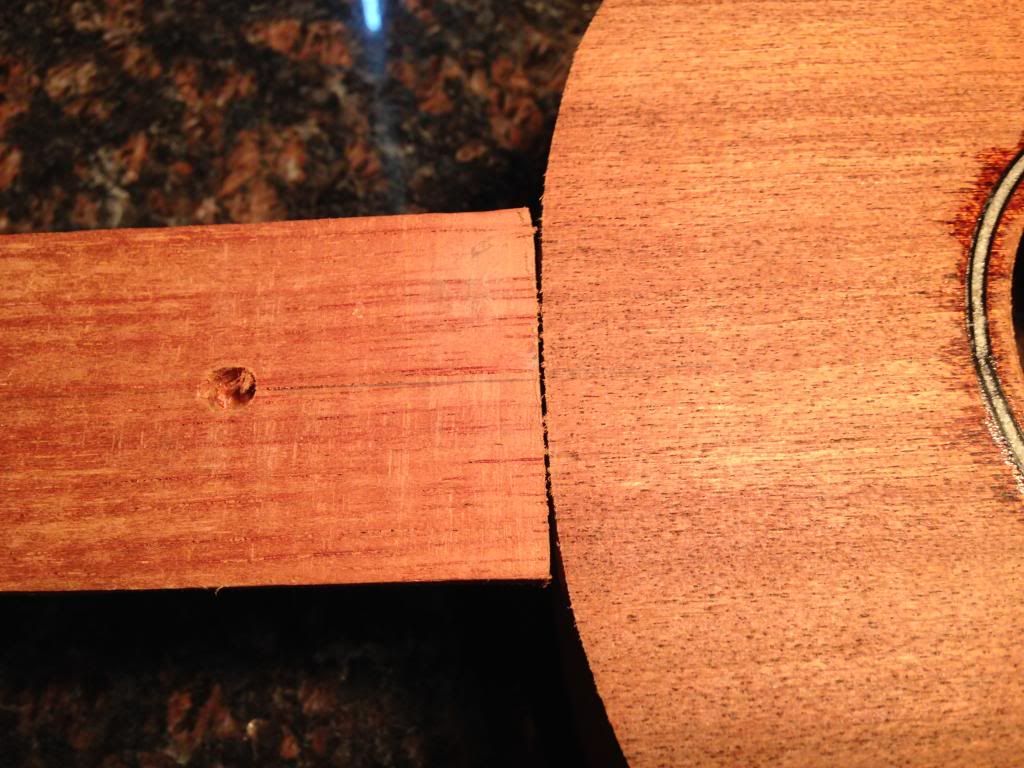
|
|
#59
05-26-2014, 09:25 PM
|
|||
|
|||
|
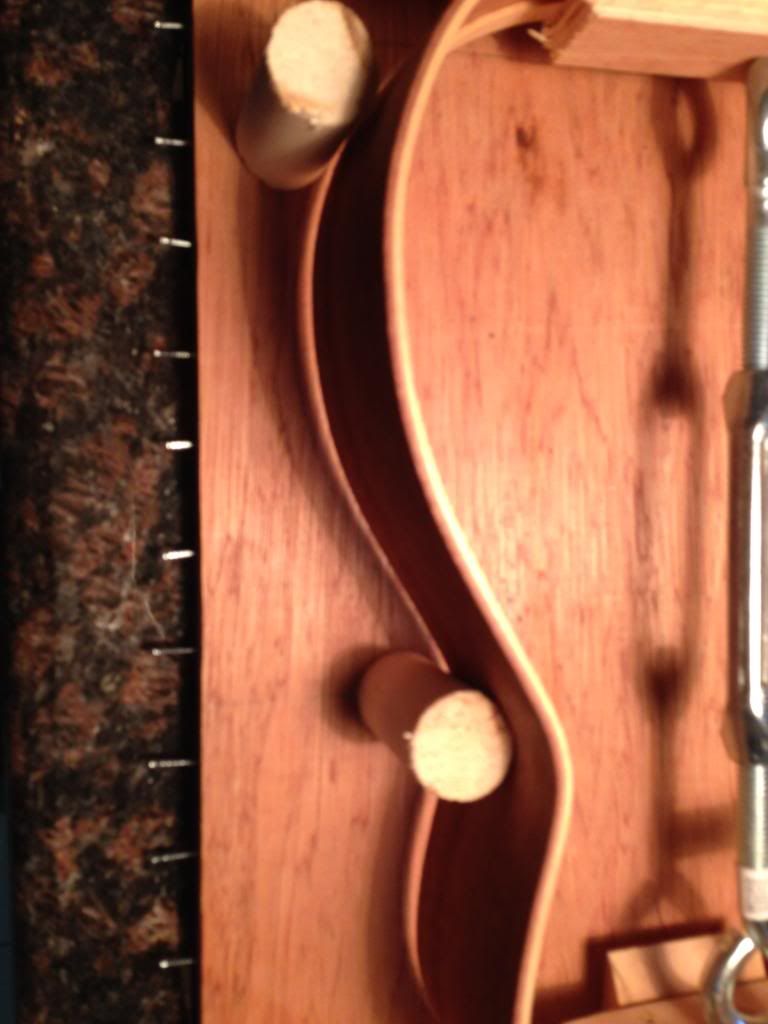
The next step is to glue on the back and close the soundbox! I didn't want another mishap occurring like what happened with the top and the rubber bands, so I made myself some spool clamps from a 1" dowel, some 6" bolts and some wing nuts.
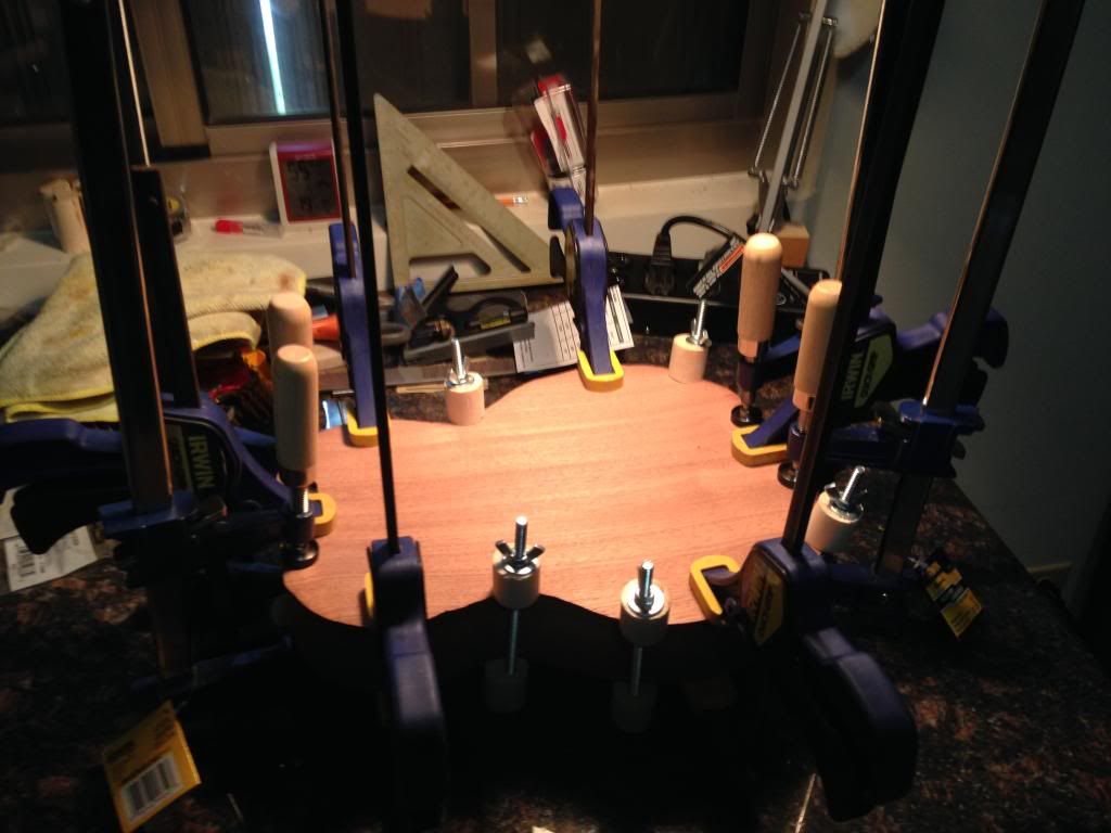 All looked really good with the light test so I glued him up, check out the great squeeze out when properly clamped. 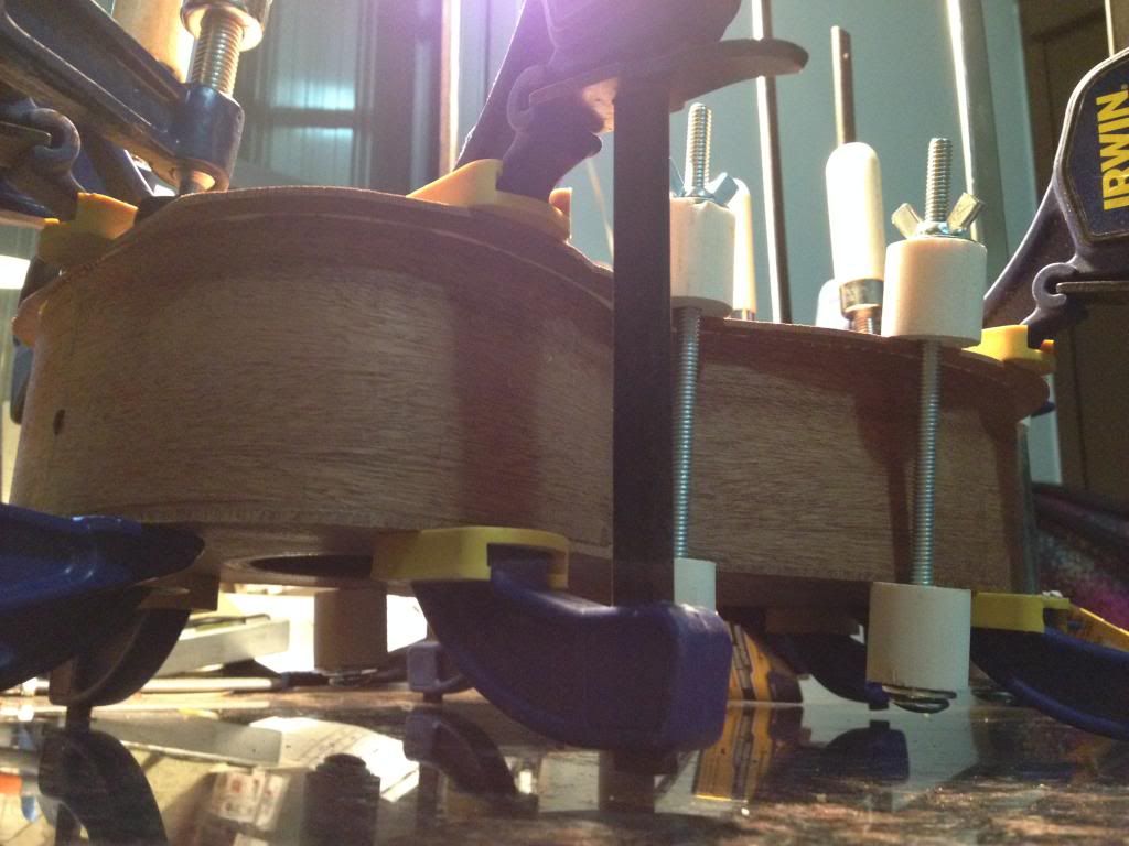 This is my first shot of the soundbox standing on its own, I was so proud! 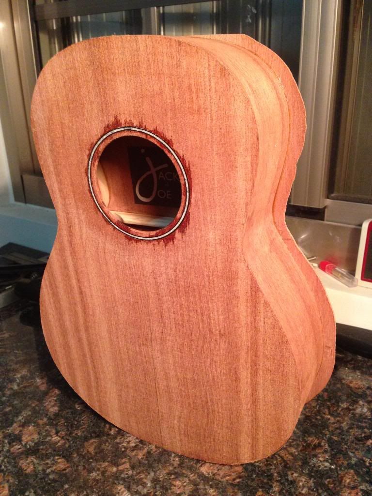
|
|
#60
05-26-2014, 09:31 PM
|
|||
|
|||
|
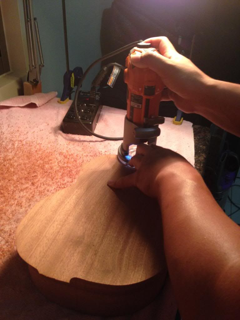
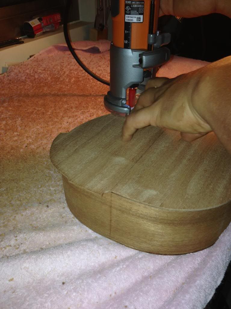
As promised, because I couldn't take pictures of when I trim-routed the top, here are the pictures Jackie took of me flush-cutting the back. Again, have to say "Thank You" to Gordon Mayer of MyaMoe ukuleles for their "Birth of a MyaMoe" YT series for the tips on how to do this correctly.
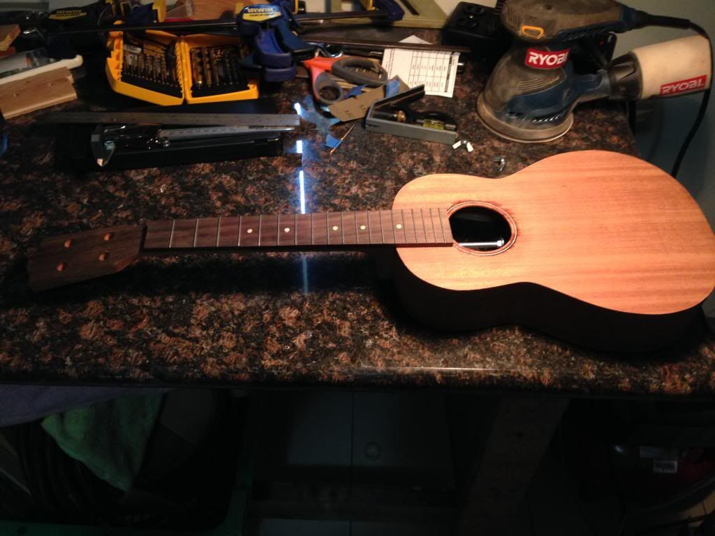
  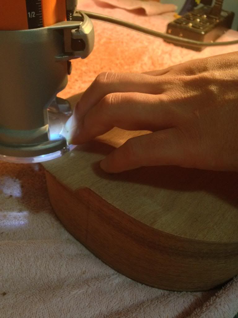 ...and here he is folks, I'm so proud of Jackie and I for making it this far! It was such an awesome feeling to look into the soundhole and see our label! 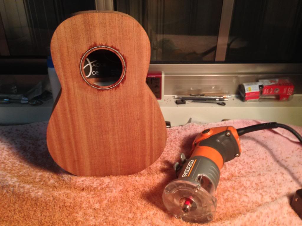
|
 |
|
| Tags |
| first build, stewmac tenor kit |
| Thread Tools | |
|
|