
|
|
#61
 06-25-2016, 02:31 PM
|
|||
|
|||
|
"Why can't you keep the pump on for three days, doesn't it cycle on and off?"
A vacuum pump is not made to be on that long, it can overheat and break. I had this pump on for 8 hours today and it becomes 70 degrees celcius on the cooling fins. A good mold can hold a vacuum and survive a droptest. This mold can not hold the vacuum, even with the fiberglass rim. I had planned to make a hard inside shell as well, but the materials for that had to be used to make this 2nd mold in an attempt to save the project when the first mold failed. You should not attempt infusion unless the mold can survive a droptest (stay in vacuum for 1 hour). I also have neighbours and i doubt they want to hear bzzzzzzzzrrrrrrr for 3 days including at night. 
__________________
build, learn, grow Last edited by littlesmith; 06-25-2016 at 02:36 PM. 
|
|
#62
06-25-2016, 03:41 PM
|
|||
|
|||
|
I am used to vacuum pumps being connected up to a holding tank and the pump cycles on and off depending on the amount of vacuum in the tank. Use your fancy sniffer to find your leak.
__________________
Fred
|
|
#63
06-25-2016, 03:54 PM
|
|||
|
|||
|
You don't need to keep it under vacuum until the resin is fully cured. Overnight is absolutely fine even for slow set epoxy, as long as the temperature is reasonable.
The edges are easier to trim when the laminate is still 'green' (rather than fully cured) too. I'd possibly be more worried about the leak. How fast is the pressure dropping and can you find out where from? If it's on the edge it's not too bad, but if it's in the middle, you'll get bubbles sucked into the laminate which won't look very good. Instead of clamping that rim all around, why not use tacky tape? It's like sealant on a roll that you can lay around the edge and get a really good seal. http://www.ecfibreglasssupplies.co.u...ling-tape.aspx If that doesn't work, try using a normal disposable vacuum bag and see if it holds pressure better. Last edited by PeterF; 06-25-2016 at 04:03 PM.
|
|
#64
06-26-2016, 07:09 AM
|
|||
|
|||
|
Quote:
Something like this :  As long as the pump is on the vacuum is on a good level, even beyond -1, so i attempted infusion,When you turn the pump off, it instantly drops to regular atmosphere. I had hoped to have a mold that can stay on vacuum. I am looking to find more money to buy epoxy that fully cures in 8 hours. I mailed the supplyer of the heating blanket and asked if i can return it, it is never used, that would give me 800 Euro. I will know in 2 days if the resin has penetrated every layer in the fabric stack, and then i can see how the surface is, hopefully no pinholes and unsaturated areas and things like that... I used infusion spray glue and antislip carbon fiber fabric (it has some glue so the edges won`t open up when it`s cut), i even called them, and he told me both of these things do not prevent saturation. Edit : somebody on instagram just donated and now i can buy this connector! ^_^
__________________
build, learn, grow Last edited by littlesmith; 06-26-2016 at 10:30 AM.
|
|
#65
06-26-2016, 07:11 AM
|
|||
|
|||
|
Removing the bag went well, it did not stick.
 Removing the peelply when the epoxy is still not 100% cured, so it is easyer to remove.  I will leave this in for 1 or 2 more days to fully cure. 
__________________
build, learn, grow
|
|
#66
06-26-2016, 02:45 PM
|
|||
|
|||
|
The first test body is full of pinholes and big airpockets. This can be adressed by putting in a breeder cloth that makes the room between the mold surface and the vacuumbag smaller.
 This is the largest airpocket in testbody 1.  Airpockets along the edge (0 line).  Gave the body a good wash in the shower to clean the excess release wax off.  Washed body.  It`s not great, but i know how to improve the quality from here, this is why it`s a test body. The money of the 10k loan maybe gone but this was calculated in the ordered fabrics.  This body is not great but the transitions between fabric pieces is great. The non slip carbon fiber outer layer prevents the fibers from opening up like with regular carbon fiber. This gives one of the advantages of prepreg in a dry fabric. 
__________________
build, learn, grow
|
|
#67
06-27-2016, 02:09 PM
|
|||
|
|||
|
I've just been looking at your setup again and thinking about how I would go about it if I were doing it.
I'm not sure if I've understood this right, but it looks like you're infusing from the outside to the inside. I think you'll get better results if you do it the other way around - have the resin input pipe(s) in the centre and suck from the outside. You'll have more margin for error of when to shut off the resin supply. Also, are you only using peel ply over the stack? That will really inhibit the resin flowing properly. I know you mentioned using a breather next time. If you use varying grades of mesh, you'll be able to control exactly how fast the resin flows out. Here's a model boat hull I did a while back. Infusing from the centre and sucking around the edge. The blue mesh is very coarse and allows resin to flow really fast up the length of the keel, where it then spread more slowly through the orange mesh up the sides. If you get the timing right, the resin should reach the top all around at the same time and you won't get any up the pipe. 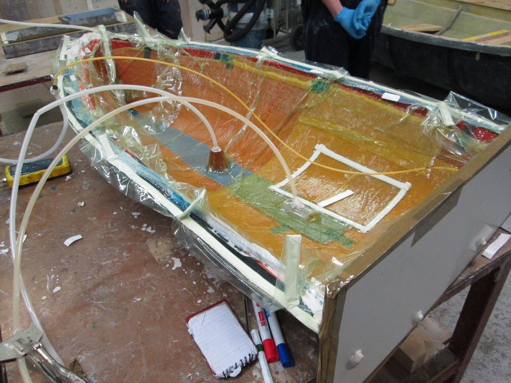 Here's a closeup of the mesh: 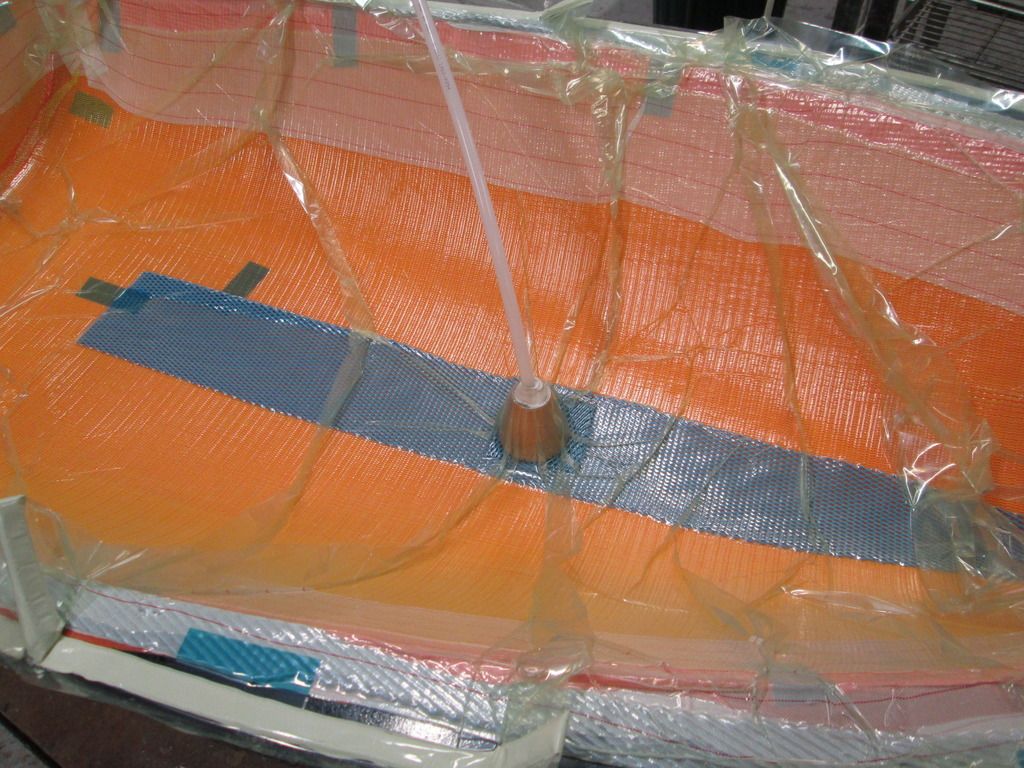 Finally, as nice as it sounds to have a reusable bag, it looks to me like more trouble than it's worth. You really need to be sure it's pressing hard against the mould, and a pre-shaped bag isn't going to do that very well. A normal thin plastic vacuum bag will give you much better and more even pressure and is a lot easier to seal.
|
|
#68
06-28-2016, 07:26 AM
|
|||
|
|||
|
Quote:
I am not making resin flow along the perimiter and sucking in the middle, so my setup is in to out like yours, not out to in. I have channels in the middle of the guitar body where the resin enters (inlet). The perimeter hose is sucking air (outlet). This MTI hose stops the resin at that point and sucks air evenly all along the mold perimiter. You have to close off 1 end off the perimiter hose, and attach a normal 6mm vacuum tube on the other going to the catchpot and then to the vacuumpump. How the MTI hose works : https://www.youtube.com/watch?v=8lKabpAMluk This is my setup :  The purple "double T" shape is the resin inlet channel. the red curved thing is the MTI perimiter hose. I had planned to make a hard inner shell as well when the mold making wax was still in there representing my part, but the first mold failed, so i needed to use the gelcoat and fiberglass and epoxy planned for the hard inner shell to make mold 2. A hard shell combined with resin out to in (opposite of us) is used in a composite technique called RTM manufacturing (fabric between 2 hard shells) : https://www.youtube.com/watch?v=f-vBw3HH7uI RTM has 2 rubber seals, they actually suck the air out of the space between these 2 rubbers, not out of the mold area. This way they are pressing down the center and it stops at stopping pillars making a consistent part every time I had hoped to have a silicone bag as well as a hard inner shell and compare the results, but this was needed to save the project. I chose the sillicone reusable bag because i always had a leak in that flimsy vacuumfilm, the needle was never on vacuum, even though this mold can`t hold a vacuum, at least the needle is far beyond vacuum (-1), so i`m happy with that. This bag is roughly 4 mm instead of a 0.5mm flimsy transparant film. I`m gonna do 1 more infusion with breeder cloth pushing the fabric agains the mold, and some infusion mesh. When i openendd this testbody 1, i saw that the hoses disconnected from the pressure, so i bought some fancy gismos :  2 of these will go in the resin distribution channel to keep the tubes together. 1 of them will get a hole drilled in the top and ill put a hose connector on it.
__________________
build, learn, grow Last edited by littlesmith; 06-28-2016 at 07:46 AM.
|
|
#69
06-29-2016, 11:44 AM
|
|||
|
|||
|
Oh ok, I thought I might have got that wrong.
I've never tried RTM, but it looks like real a pain to do unless you happen to have a 5 axis CNC machine. That inner mould has to be absolutely perfectly matched to the laminate stack you're using or you won't get a properly consolidated part. The only real benefit I can see is getting a part that's shiny and smooth inside and out.
|
|
#70
06-30-2016, 08:45 AM
|
|||
|
|||
|
Quote:
I`m having major air pockets in the body, i build up a second body today in the mold (dry with spray glue), tomorrow i will make body nr2 with infusion, there is bleeder cloth in it now to push the fabric. I have to start early in the day so i can keep the pump on for a long time. I have to turn it off around 21:00 for the neighbours. I wish i had a shop, but for now this is not a company and just at home.
__________________
build, learn, grow Last edited by littlesmith; 06-30-2016 at 05:31 PM.
|
|
#71
07-03-2016, 09:14 AM
|
|||
|
|||
|
Making composite body 2.
 Body 2 has some breether cloth.  This is the new connection with a cross connector with a hole in the top for the resin inlet.  Infusion of body 2.  There was an error in the process, the resin in the back did not go up. I am not 100% sure why but i suspect that the fiberglass rim clamped the MTI hose, i have marked where this happens and i will cut pieces out of the rim. Hopefully this will prevent it next time.  As i suspected (you can see it in the last picture), the resin didn`t go up all the way, leaving an area of fabric unsaturated. I left the body in the mold and wetted it from 2 sides.  The wetted repair area.  The new connectors worked, the resin was distributed nicely.  Body 2.  2 little buddys! 
__________________
build, learn, grow
|
|
#72
07-27-2016, 04:16 PM
|
|||
|
|||
|
Little update, it`s been a while.
The project ran out of money because the first mold failed. That ate up the reserves. I returned an 800 euro heating blanket, somebody also suggested this on the forum. Even though the infusion exposy says mandatory heat curing on the bottles and pamflets, it is still very hard and dimentionally stable without it. This money allows me to continue the project. I could have made the 8 composite unibodys with the mold and the reusable vacuumbag but they are not comoing out perfectly. Those 2 bodies havd 100s of tiny holes and some big airpockets, that could be repaired but i want to tweak the system further so the bodys come out nice consistently. I prepped the mold with wax sheets to make a hard inner shell, but the gelcoat was too thick and reached temperatures of 122 degrees celcius on some areas (251 Fahrenheit). That warped the gelcoat making it useless. It also melted the wax sheets. I now have new gelcoat that stays around 30 degrees, even with a lot of mass.   When the inner hard shell is done it should eliminate the larges airpockets because the dry fabric is now forced between 2 hard surfaces. If it doesn work i determin which gives a better result and go with that. If i have to fill and sand bodies for 20 hours per body i will, but i rather have the process correct. I`m also making a nice routerbox so the bodys can be trimmed and have a 100% level top.  There will be a hole in the top plywood and the ballbearing routerbit will travel along the edge, directly above the body edge.  This picture makes it clear why bodys have to be routed.  
__________________
build, learn, grow
|
|
#73
07-31-2016, 01:34 PM
|
|||
|
|||
|
Making a body holder for the routing box.
    The second attempt of the hard inner shell. Building wax sheets for the 3rd time to represent part thickness.  Adding layers of paper tape to represent the thickness of the peelply fabric and infusion mesh.   These tiny holes in the calibrated wax sheets are depth stops. The entire edge of the mold is also a depth stop.  The resin infusion channel is taped down with blue tape and the gelcoat is added.   The fiberglass is added for the hard inner shell mold. I did not use a dye in the gelcoat or epoxy that is in the fiberglas to see the resin flowing during the infusion process. 
__________________
build, learn, grow
|
|
#74
08-01-2016, 08:07 AM
|
|||
|
|||
 Pultruded carbon fiber square tube for dimentional stability for the hard inner shell mold.
__________________
build, learn, grow
|
|
#75
08-05-2016, 01:58 PM
|
|||
|
|||
|
The edge of this component got destroyed. Delamination of the gelcoat during the release process. I have to repair this part before it can be used.
 This is how the routing box will work : The ballbearing of the routerbit will travel along this edge and trimm off the excess carbon fiber that went over the edge of the mold. You need this flange for the release process to get the body out of the mold. This routing operation will also create a level line which is the underside line of the fretboard as well as the top line of the soundboard.  Glueing wooden boxes on the fiberglass body holders.  This arch prevents that the center sags down from the weight of the router.  A 16 degree plane is made for the headstock routing surface  This is how the drawer extends to put bodys in and out to route them. The slider mechanism for this drawer extends it`s own full length so it is easy to put a body in to route. You do have to support the weight of the drawer.  Pretty, work of art tool! This is a closeup of 1 of 4 threaded bars to make the body higher or lower for routing. 
__________________
build, learn, grow
|


