
|
|
#76
 02-20-2024, 06:12 PM
|
|||
|
|||
|
I used it today at my duo practice and loved it! Also, StewMac sent me a very detailed suggestion (including an annotated version of one of my pictures!), which is simple to implement, to reduce the reverb hum (at high levels I would never use). Their fix points out it's a ground loop in the V3b reverb mixer (reverb is injected into the mixer's grid bias circuit from the front panel pot). I was fixated on the V3a reverb recovery.
[Edit: However, it did not work, and grounding the reverb recovery triode's output, after the DC blocking cap, does kill the hum. It's the recovery triode. I'm going to leave the chassis out for a while and work with StewMac. Being a perfectionist has its downsides :~)] [Edit 2: Pulled the V3 tube, reverb recovery and mix, and powered up the amp. Dead silent! The output stage is perfect. I then checked the V3a recovery tube cathode lead for AC leakage, from the adjacent filament supply pin. There was none. No AC on the cathode. The socket is good. Next suspect: the high voltage supply to V1, V3, and V4a, all the signal carrying preamp tubes except the reverb driver which is clearly not the problem.] [Edit 3: Extra capacitance on the power supply made no difference. If I "10" the reverb, I still get 50 mV of 120 Hz hum. This is less than a milliwatt. I guess it's time to button it up and play guitar.]
__________________
jf45ir Free DIY Acoustic Guitar IR Generator .wav file, 30 seconds, pickup left, mic right, open position strumming best...send to direct email below I'll send you 100/0, 75/25, 50/50 & 0/100 IR/Bypass IRs IR Demo, read the description too: https://youtu.be/SELEE4yugjE My duo's website and my email... [email protected] Jon Fields Last edited by jonfields45; 03-05-2024 at 08:51 AM. 
|
|
#77
02-24-2024, 10:33 AM
|
||||
|
||||
|
[QUOTE=jonfields45;7407450]At this point, I’m in complete agreement. I’m paranoid that stripping the wire, as instructed in the assembly manual, left slight damage to the core and made broken flying leads more likely. Hopefully at this point not relevant to future reliability.
Silly me when I built my Mojo PR kit I I decided to try stripping the cloth according to the instructions. Over time the several wires broke because if they are ever so slightly nicked by your stripper they will break. Solved the problem by replacing the cloth pushback wire with mil surplus Teflon insulated silver plated stranded copper hookup wire. Problem solved  By the way I reached out to StewMac and told them about the wire breakage due to following their instructions about stripping the cloth ends. I'm surprised to learn that they still recommend stripping the cloth insulation. There is a reason it is called "pushback wire". If you go to Rob Robinette's website he has pages devoted to how the Princeton Reverb works. He includes info on recommended modifications. FWIW I strongly recommend the mod that makes the fixed bias adjustable by adding a potentiometer. There is also useful information about grounding schemes. The Mojo grounding scheme can easily be improved on. My PR build doesn't hum at all! Adding a phase inverter grid stop resistor is easy and improves the sound of the amp when you overdrive it. Enjoy your new amp
Last edited by Al Acuff; 02-24-2024 at 10:49 AM.
|
|
#78
02-24-2024, 03:11 PM
|
|||
|
|||
|
This video covers more things than my little problem, but it seems to have the right fix for me and he demonstrates similar hum as he turns up the reverb.
https://youtube.com/watch?v=piDDIBCP...e3_kDOWuidLfKQ I need to move the V3 and V4 bias grounds from the same ground point which also has the main power supply electrolytics attached. The dead quiet V1 input stage and V2 reverb transformer driver get their grounds from the input jacks (two massive lock washers to the chassis and no current flow to speak of). I’m out of town for the week so this is going to wait a bit. If I 10 the reverb I get 50 mV of 120 Hz hum on the speaker. Working back to the grid of the V3a reverb recovery triode that’s only ~~6 uV. V3a’s grid bias point ground is the chassis ground at the reverb send RCA jack. Just 6 uV working its way from the power supply ground via the eyelet daisy chain to the V3a cathode bias point ground would be a nice little ground loop in a high gain path. I don’t share his enthusiasm for the brass plate; easy to solder to, but prone to corrosion.
__________________
jf45ir Free DIY Acoustic Guitar IR Generator .wav file, 30 seconds, pickup left, mic right, open position strumming best...send to direct email below I'll send you 100/0, 75/25, 50/50 & 0/100 IR/Bypass IRs IR Demo, read the description too: https://youtu.be/SELEE4yugjE My duo's website and my email... [email protected] Jon Fields Last edited by jonfields45; 03-05-2024 at 04:57 AM.
|
|
#79
02-25-2024, 10:32 AM
|
||||
|
||||
|
Looking back at your build photos your grounding scheme is probably respnsible for your hum. This article will school you on grounding. I recommend the optimized Princeton Reverb grounding scheme that Rob Robinette diagrams on the webpage I linked you to.
http://www.valvewizard.co.uk/Grounding.pdf FWIW here is a photo of the wiring in my PR kit build. Note the heavy gauge tinned solid copper ground bus for the preamp section. It's hard to see because of the photo size upload limit but it's also significant that the filament wires are wired in phase from socket to socket. Last edited by Al Acuff; 02-26-2024 at 09:13 AM.
|
|
#80
02-26-2024, 10:24 AM
|
|||
|
|||
|
Quote:
For 10 years of my EE career I managed mix signal IC design and the application support for those products. I have plenty of experience with good grounding designs that worked and hit a price point. I thought the eyelet board ground wiring was sketchy from the beginning, but the kit was advertised as a fairly exact copy of a 60+ year old design with extensive sales. So who was I to judge?
__________________
jf45ir Free DIY Acoustic Guitar IR Generator .wav file, 30 seconds, pickup left, mic right, open position strumming best...send to direct email below I'll send you 100/0, 75/25, 50/50 & 0/100 IR/Bypass IRs IR Demo, read the description too: https://youtu.be/SELEE4yugjE My duo's website and my email... [email protected] Jon Fields Last edited by jonfields45; 02-27-2024 at 06:56 AM.
|
|
#81
03-03-2024, 07:56 PM
|
|||
|
|||
|
Reverb 10, Volume 1, 50 mV 120 Hz noise on speaker, reverb spring disconnected.
 Reverb 10, Volume 1, 20 mV 120 Hz noise on speaker. Apparently the power supply ground spikes enough current into the central ground connection to make it too noisy for the preamp. I moved the right eyelet board ground to an independent chassis connection. The left eyelet board ground already has a private chassis ground at the input jacks. I had hoped this would be all that was needed.  The next step was grounding the eyelets to the chassis which are daisy chained from the sides. I put these lugs on the volume, treble, bass, and reverb pots to give me solderable chassis ground points. This was instead of a brass front panel board (which is easily solderable but corrodes) or some other improvised ground bar. 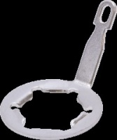 Reverb 10, Volume 1, 6 mV noise on speaker (my meter reads 3 mV with its probes shorted together). I soldered a jumper to the back of each pot from the solder lug, and added two jumpers to the ground eyelets not already directly connected to the chassis. BTW, with the reverb off, and the volume at 10, I also get a 6 mV reading.   Nothing in life is as simple as it should be. I reconnected the reverb spring and suddenly had 28 mV of 60 Hz noise. The reverb return cable was not making a good ground connection. After I scraped myself off the basement ceiling it was an easy fix. I decided to order some gold plated RCA cables and gold plated RCA jacks off Amazon. If the cables seem stable, then I'll button up the amp as is. If not, the new jacks go in.
__________________
jf45ir Free DIY Acoustic Guitar IR Generator .wav file, 30 seconds, pickup left, mic right, open position strumming best...send to direct email below I'll send you 100/0, 75/25, 50/50 & 0/100 IR/Bypass IRs IR Demo, read the description too: https://youtu.be/SELEE4yugjE My duo's website and my email... [email protected] Jon Fields
|
|
#82
03-04-2024, 05:51 PM
|
|||
|
|||
 The new cables to the reverb tank did the trick. It is quiet, sounds great, and IMHO finished.
__________________
jf45ir Free DIY Acoustic Guitar IR Generator .wav file, 30 seconds, pickup left, mic right, open position strumming best...send to direct email below I'll send you 100/0, 75/25, 50/50 & 0/100 IR/Bypass IRs IR Demo, read the description too: https://youtu.be/SELEE4yugjE My duo's website and my email... [email protected] Jon Fields Last edited by jonfields45; 03-05-2024 at 07:34 PM.
|
|
#83
03-06-2024, 04:46 AM
|
|||
|
|||

__________________
jf45ir Free DIY Acoustic Guitar IR Generator .wav file, 30 seconds, pickup left, mic right, open position strumming best...send to direct email below I'll send you 100/0, 75/25, 50/50 & 0/100 IR/Bypass IRs IR Demo, read the description too: https://youtu.be/SELEE4yugjE My duo's website and my email... [email protected] Jon Fields
|
|
#85
03-06-2024, 06:38 AM
|
|||
|
|||
|
Quote:
A total win during the usually dreary PA winter!!!
__________________
jf45ir Free DIY Acoustic Guitar IR Generator .wav file, 30 seconds, pickup left, mic right, open position strumming best...send to direct email below I'll send you 100/0, 75/25, 50/50 & 0/100 IR/Bypass IRs IR Demo, read the description too: https://youtu.be/SELEE4yugjE My duo's website and my email... [email protected] Jon Fields
|
|
#86
03-13-2024, 05:01 PM
|
|||
|
|||
 This is off to be printed 12x36" matte finish to be hung over my soldering work bench.
__________________
jf45ir Free DIY Acoustic Guitar IR Generator .wav file, 30 seconds, pickup left, mic right, open position strumming best...send to direct email below I'll send you 100/0, 75/25, 50/50 & 0/100 IR/Bypass IRs IR Demo, read the description too: https://youtu.be/SELEE4yugjE My duo's website and my email... [email protected] Jon Fields
|
|
#88
04-23-2024, 06:47 AM
|
|||
|
|||
|
I evaluated the various possible mods to my Princeton and decided to do none of them. I did measure the output tube biasing and found it to be quite close to the "recommended" 70% of the 14-watt plate dissipation rating for a 6V6GC in an AB configuration. Old RCA tube manuals a friend owns recommend 50-80%. Numbers and algebra far below if anyone is interested... More boring details:
Looking through the options, beyond the grounding problem I documented in previous posts, here are the heavy hitters in online chatter:
Here are the details of the bias measurement I made (8 ohm wire wound dummy load, all the controls at 1). Node/Spec --- V5 6V6 --- V6 6V6 --- Unit --- Variable B+ --- 373.2 --- 373.2 --- volts --- B, measured Plate --- 369.0 --- 369.3 --- volts --- P, measured Grid --- -26.8 --- -26.8 --- volts --- G, measured Plate to B+ --- 159.6 --- 142.9 --- ohms --- R, measured Bias Current --- 0.026 --- 0.027 --- amps --- C = (B - P) / R, calculated % 14 watts --- 69% --- 72% --- NA --- C * P / 14, calculated
__________________
jf45ir Free DIY Acoustic Guitar IR Generator .wav file, 30 seconds, pickup left, mic right, open position strumming best...send to direct email below I'll send you 100/0, 75/25, 50/50 & 0/100 IR/Bypass IRs IR Demo, read the description too: https://youtu.be/SELEE4yugjE My duo's website and my email... [email protected] Jon Fields Last edited by jonfields45; 04-24-2024 at 08:06 PM.
|


